Safety Management in BMD Vehicles
Safety Management in BMD Vehicles
: Dr. Manoj K Patel :

: Dr. Manoj K Patel :

INTRODUCTION:
With the inception of manufacturing of SME and ANFO in large mines like Moher and Moher
Amlorhi OC Coal Mines of Reliance; coal mines of SCCL, Singareni; NCL,
Singrauli, etc; the BMD Vehicles; used for transportation and charging of SME
and ANFO; have entered into the gambit of
mining machineries. Unlike other machineries and HEMM used in the mines,
the BMD Vehicles will attract more attention to mines management as well as
statutory authorities because of the hazardous material carried and used by
these vehicles, inside and outside the mine premises. These vehicles are
smaller compared to the HEMM but the risk involved in these are many folds
compared to that of HEMM. Keeping these aspects in mind the authors have tried
to bring out details safety hazard aspects associated with these BMD Vehicles.
EMULSIONS
and ANFO are SAFE – A MYTH:
The myth with SME and ANFO is that – these are safe. Emulsions are
basically not sensitive in the same way that nitro-glycerine, PETN and lead
azide etc are. They show no sensitivity to detonate when subjected to the
normal levels of friction, impact, static and heat etc. found in a plant
environment. Therefore it is assumed that not only are they safer – they are
inherently safe. Here lies the problem. Are they safer? Yes. Are they safe? No - not if by “safe” we
mean they will not detonate or explode in a fault condition in a plant
environment. The reason we have a problem is because the behaviour of emulsions
in certain plant situations is not correctly understood by many of the people
who handle them. To understand their behaviour we need to look at the materials
that are used in emulsion processes, their properties and how they can interact
with the process and equipment.
Ammonium Nitrate Porous Prills (ANPP):
ANPP has a melting point of 170 ⁰C and it decomposes above 210 ⁰C.
During normal handling, ammonium nitrate does not explode due to the friction
but it can be detonated under heat and confinement or severe shock. ANPP is
classified as dangerous goods class 5.1 oxidizing substances, UN1942. Ammonium
nitrate must not contain more than 0.2 % combustible material. AN’ s thermal
conductivity is extremely low and its heat capacity is relatively high,
implying that quite high amounts of heat must be applied to melt it. At
elevated temperatures, several alterations can be observed with AN. First of
all, the crystal structure of AN changes at 32 °C going from porous grains to a
more powder-like form. This can have a sensitizing effect. Melting point o AN is
approximately 170 °C, however, an extremely slow endothermic decomposition can
be observed from 80–90 °C. The products forming from this decomposition is
ammonia and nitric acid:
NH4NO3(s) → NH3(g) + HNO3(g)
When
the temperature exceeds AN’s melting point and approaches its boiling point
(210 °C), a second exothermic decomposition can take place, yielding nitrous
oxide and water:
NH4NO3(l) → N2O(g) + 2H2O(g)
Temperatures
above the boiling point accelerate the decomposition of AN. Furthermore,
poisonous red/ brown NOx gasses can be formed. This decomposition can be of
explosive nature.
SME or Ammonium Nitrate base Emulsion
(ANE or SME): The ammonium nitrate emulsion (ANE) manufactured
with emulsifiers creates a petroleum jelly-like mixture. The emulsion is oil continuous
(Water in Oil Type Emulsion) and thus is not miscible with water. AN is
classified as class 5.1 oxidizing agent and is transported as dangerous goods
UN3375. ANE (SME) mostly consists of diluted AN and can, when heated,
theoretically lead to similar decomposition patterns like ANPP. If the water in
ANE (SME) can evaporate, the resulting mixture will be similar to that
of ANFO. This could have a greater explosive potential under fire exposure than
ANPP alone. Thus, by heating ANE (SME), especially under confinement, the
explosion hazard will be greater. If the AN in this mixture starts do
decompose, the mixture can basically sensitize itself by “self-gassing” leading
to a mixture with lower density and greater sensitivity. Contaminations in ANE
(SME) will have similar effects on ANE (SME) as it happens for ANPP.
Acetic Acid: Acetic
acid is a carboxylic acid which is a weak acid with a boiling point between
118-119 °C. Acetic acid above 10% is classified as a corrosive, flammable
liquid. It has a flashpoint at 69 °C. The acetic acid functions as a catalyst
in the sensitizing process in the explosives mixture, providing the desired
density. It is non-compatible with oxidizing agents. High temperatures and open
flames should be avoided. Heating can produce flammable gasses.
Diesel Oil (HSD):
It has a boiling point 215-376°C and it does not decompose. It has a
lower flashpoint at 60 °C. It is highly
hazardous in the close proximity of heat and sources of ignition. Storage tanks
need to be provided with proper earthing, ground/bond line and equipment during
pumping or transfer to avoid the accumulation of static charge. BMD Vehicles
usually have two diesel oil tanks used for truck fuel and explosives
manufacturing, respectively. Diesel oil is a petroleum-based fuel consisting of
both saturated and aromatic hydrocarbons.
Paraffin Wax:
Wax has a melting point of 37⁰C and it does not decompose. It is a
diverse class of organic compounds that
are hydrophobic, malleable solids
at ambient temperatures. It is hazardous in close proximity to oxidisers and
heat.
Sodium Nitrite: It
is in-compatible to reducing agents, combustible materials, organic materials,
metals, acids, alkalis, and oxidizer. It classified as oxidizing, toxic and
environmentally damaging. Sodium nitrite is used as a sensitizer due to its
reaction with AN which produces nitrogen gas.
The
explosive hazard of sodium nitrite is much lower than for its corresponding
nitrates; however, explosive mixtures can be formed when combined with ammonium
salts, pulverized metals or combustible materials. The melting point of sodium
nitrate is 280 °C. When temperatures exceed 320 °C, sodium nitrate becomes
unstable and starts to decompose producing sodium oxide, nitrogen(II) oxide and
nitrogen dioxide:
2NaNO2
(l) → Na2O (s) + NO (g) + NO2 (g)
INCOMPATIBILE CHEMICALS
used in ANFO and SME:
In-compatibility of the chemicals
used during transportation, manufacture and charging of ANFO and SME in the
blast holes is:
Compatability
List for Raw Materials
|
||||||||||
Ammonium Nitrate (Solid)
|
Ammonium Nitrate (Liquid)
|
Sodium Nitrate
|
Sodium Nitrite
|
Wax
|
Salt
|
Acetic Acid
|
HSD
|
Furnace Oil
|
SMO
|
|
Ammonium
Nitrate |
ü
|
X
|
ü
|
X
|
ü
|
ü
|
X
|
X
|
X
|
X
|
Sodium
Nitrate |
ü
|
X
|
X
|
X
|
X
|
X
|
X
|
X
|
X
|
X
|
Sodium
Nitrite |
X
|
X
|
X
|
X
|
ü
|
ü
|
X
|
X
|
X
|
X
|
Wax
|
ü
|
X
|
ü
|
ü
|
ü
|
ü
|
X
|
X
|
X
|
X
|
Salt
|
ü
|
X
|
ü
|
ü
|
ü
|
ü
|
ü
|
X
|
X
|
X
|
Acetic
Acid |
X
|
X
|
X
|
X
|
X
|
X
|
ü
|
X
|
X
|
X
|
HSD
|
X
|
X
|
X
|
X
|
X
|
X
|
X
|
ü
|
X
|
X
|
Furnace
Oil |
X
|
X
|
X
|
X
|
X
|
X
|
X
|
X
|
ü
|
X
|
SMO
|
X
|
X
|
X
|
X
|
X
|
X
|
X
|
X
|
X
|
ü
|
So,
ANFO, HANFO, and SME are NOT safe. They
are a bit safer than PETN, TNT and Lead Azide etc.
BMD VEHICLES:
BMD
Vehicles are mainly of two types, (1) the SME BMD Vehicles and (2) the ANFO
BMD Vehicles. Additionally, there is a third category for a vehicle for product
Heavy-ANFO or more commonly known as HANFO. So, the third category is (3) the
HANFO BMD Vehicle. Now coming over to the SME BMD Vehicles, it is further
divided as Straight SME BMD Vehicle and the Doped SME BMD Vehicles. In this
paper we are going to consider safety aspects of all the 04 types of BMDs,
namely, (1) The Straight Emulsion BMD, (2) The Doped Emulsion BMD, (3) The ANFO
BMD, and (4) The HANFO BMD.
The
BMDs are designed to provide a mobile unit for transporting bulk emulsion
explosives along with proportionate quantity of gassing agent and or Ammonium
Nitrate and Diesel Oil carried in separate compartments. In the blasting site,
the unit will mix the desired materials together and mechanically deliver it
into a blast hole.
These
BMDs feature stainless steel construction of Emulsion bin, bottom auger and
gassing agent tank and maybe one or more tanks to carry AN and HSD. Body
spring mounts allow the chassis to flex to minimize stresses, prolonging body
life. The complete hydraulic system features tank, suction and return line
filters, hydraulic pump for reliability, and long life. The complete fuel system
has a reinforced tank and hydraulic-drive fuel pump for accurate oil ratio mix,
with totalizer to count fuel delivered. Electronic counter systems are
available to monitor mix delivery. Bin of different quantity is available, with
augers sized to suit delivery rate requirements. The emulsion is loaded into
the emulsion bin from the storage SILO, water for gassing solution along with
gassing agent.
1) BMD
for Straight Emulsion:
COMPONENT
|
SPECIFICATION
|
Emulsion Bin
|
The Rectangular bin is fabricated from SS-304 Plates. The bottom of the
bin is conical with an auger at the bottom. The auger is fitted with flanged
bearing; drive hydraulic motor, support structures with a subframe for chassis
mounting.
|
Gassing Agent Bin
|
The Rectangular bin is fabricated from SS-304 plates. The bottom of the bin is flat and the outlet is having a valve with a strainer and connected to the inlet of the gassing agent pump. The bin will also feature all necessary
nozzle, level indicator, etc.
|
Water Bin
|
Rectangular bin in SS 304 complete with outlet valve .The bin feature
all necessary nozzle, level indicator etc.
|
Hydraulic Oil Tank
|
The rectangular tank is fabricated from MS plates. It will have filler breather cum pouring strainer, Level indicator with a thermometer, return line filler,
outlet nozzle with a suction strainer, and gate valve. Capacity-500 liters or as desired.
|
Static Mixer
|
A static mixer is a
precision-engineered device for the continuous mixing of fluid materials
fabricated from SS304.
|
2) BMD
for Doped Emulsion:
These BMDs usually have the following
specifications:
COMPONENT
|
SPECIFICATION
|
Emulsion Bin
|
The Rectangular bin is fabricated from SS-304 Plates. The bottom of the
bin is conical with an auger at the bottom. The auger is fitted with flanged
bearing; drive hydraulic motor, support structures with subframe for chassis
mounting. Capacity-12 MT or as desired.
|
Gassing Agent Bin
|
Rectangular bin is fabricated from SS-304 plates. The bottom of the
bin is flat and the outlet is having a valve with strainer and connected to
the inlet of gassing agent pump. The bin will also feature all necessary
nozzle, level indicator, etc. Capacity-400 liters or as desired.
|
AN Bin
|
Rectangular bin is fabricated from SS-304 Plates. The bottom of the
bin is conical with auger at the bottom connected to discharge auger through
an inclined auger. The auger is fitted with flanged bearing; drive hydraulic
motor, support structures with sub frame for chassis mounting. Capacity-02 MT
or as desired.
|
Water Bin
|
Rectangular bin in SS 304 complete with outlet valve .The bin feature
all necessary nozzle, level indicator etc. Capacity- 600 liters or as
desired.
|
Hydraulic Oil Tank
|
Rectangular tank is fabricated from IS226 plates. It will have filler
breather cum pouring strainer, Level indicator with thermometer, return line
filler, outlet nozzle with suction strainer and gate valve. Capacity-450
liters or as desired.
|
Hose Lube Tank
|
Rectangular tank in SS 304 complete with outlet valve .The bin feature
all necessary nozzle, level indicator etc. Capacity- 600 liters or as
desired.
|
Diesel Tank
|
Rectangular bin in SS 304 complete with outlet valve .The bin feature
all necessary nozzle, level indicator etc. Capacity- 200 liters or as
desired.
|
3) BMD
for ANFO:
These BMDs will have the following
specifications:
COMPONENT
|
SPECIFICATION
|
AN Bin
|
Rectangular bin is fabricated from SS-304 Plates. The bottom of the
bin is conical with auger at the bottom connected to discharge auger through
an inclined auger. The auger is fitted with flanged bearing; drive hydraulic
motor, support structures with sub frame for chassis mounting. Capacity-10 MT
or as desired.
|
Hydraulic Oil Tank
|
Rectangular tank is fabricated from IS226 plates. It will have filler
breather cum pouring strainer, Level indicator with thermometer, return line
filler, outlet nozzle with suction strainer and gate valve. Capacity-450
liters.
|
Diesel Tank
|
Rectangular bin in SS 304 complete with outlet valve .The bin feature
all necessary nozzle, level indicator etc. Capacity- 500 liters or as
desired.
|
4) BMD
for HANFO:
These BMDs will have the following specifications:
COMPONENT
|
SPECIFICATION
|
Emulsion Bin
|
Rectangular bin is fabricated from SS-304 Plates. The bottom of the
bin is conical with auger at the bottom. The auger is fitted with flanged
bearing; drive hydraulic motor, support structures with sub frame for chassis
mounting. Capacity-04 MT or as desired.
|
AN Bin
|
Rectangular bin is fabricated from SS-304 Plates. The bottom of the
bin is conical with auger at the bottom connected to discharge auger through
an inclined auger. The auger is fitted with flanged bearing; drive hydraulic
motor, support structures with sub frame for chassis mounting. Capacity-10 MT
or as desired.
|
Water Bin
|
Rectangular bin in SS 304 complete with outlet valve .The bin feature
all necessary nozzle, level indicator etc. Capacity- 600 liters or as
desired.
|
Hydraulic Oil Tank
|
Rectangular tank is fabricated from IS226 plates. It will have filler
breather cum pouring strainer, Level indicator with thermometer, return line
filler, outlet nozzle with suction strainer and gate valve. Capacity-450
liters or as desired.
|
Diesel Tank
(Optional)
|
Rectangular bin in SS 304 complete with outlet valve .The bin feature
all necessary nozzle, level indicator etc. Capacity- 500 liters or as
desired.
|
HAZARDS INVOLVED in SME,
ANFO and HANFO BMD Vehicles:
An
SME, or an SMS, or an ANFO BMD Vehicle manufactures explosives at the bench (blast
site) directly into the loading hose and bore hole. All these units are mounted
on trucks, having capacities ranging from 5 – 15 tons. The Units are
fabricated on skid and the skids are mounted on truck chassis.
The system consists of truck mounted
storage and processing equipment for carrying ingredients from base plant and
mixing the ingredients at the site in required proportion. They are pumped out
as final product at the point of use. The system design permits addition of
various additives such as sensitizers, gassing agents etc. as per process
requirements. The system is powered by Hydraulics. The hydraulic drive is
powered by the truck's internal combustion engine through a power take-off shaft.
The system design ensures the safety of operation and flexibility of process
control parameters such as products, proportions, and discharge rate. The final
product after processing ingredients is pumped directly into the drilled holes
in the mines through an anti-static hose which is wound on a Hose Reel fitted
on the pump truck. The Hose can be immersed right up to the entire depth of
mine hole and subsequent withdrawal rate and charging rate can be pre-programmed. This facility ensures even charging of explosives and avoids
agglomeration at the bottom of the pit. Thus it ensures optimum usage of explosives.
The entire module is designed in such a fashion to ensure easy mobility and
safe maneuverability of fully loaded truck absolutely keeping in mind the norms of
road safety and regulations.
History
of AN, ANFO, HANFO, and SME is laden with incidences of explosions and accidents
which are not clearly understood. A literature survey will provide a good list of
such disastrous accidents in supposedly safe AN and ANFO and SME. We shall like to give one example:
The incident happened in Drevja,
Norway on 17th December 2013. The BMD
unit for on-site production of bulk explosives owned by Maxam, MEMU F-114,
arrived at Drevja on 17th December 2013 at approximately12:00, after a 160 km
transfer from the depot at Brønnøy Kalk, Norway. F-114 was carrying precursors
for production of bulk explosives, and the main components being ANPP and ANE.
The production was initiated and at approximately 13:00, a fire was identified
on the right side at the front of the vehicle. After ending an unsuccessful
attempt to extinguish the fire, the construction site and residential homes in
the immediate area were evacuated. The police and the fire brigade were alerted
and arrived at the site. The duration of the fire was approximately 2.5 hours.
It is likely that after about 1.5 hours, the fire had spread to the ground
beneath and in front of the vehicle. After about 2 hours, the fire had enclosed
the entire vehicle. The final 5 minutes, after about 2 hours and 21 minutes up
to the moment of explosion, the fire intensified significantly. There was
considerable material damages to the surrounding environment after the
explosion. A residential home burned to the ground, several buildings had
structural damages and broken windows, and construction equipment in the area
was damaged. No persons were injured.
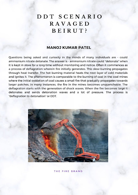
Few
photographs taken during the investigation of the “BMD Vehicle – post-blast” are
scary; and speak volume about the need of safety required in operating the BMD
Vehicles.


(Beginning of the Fire) (The Engine Block)


(Part of the vertical augur) (Part of the horizontal augur)


(Fragments found at approx 170 m away)


(Product Pump) (Part of the Production Diesel tank)
Such
are the hazards associated with seemingly and presumably safe AN, ANFO, HANFO
and SME. It can spell disaster on human life, environment, and economy of the
organization. So one has to be extremely careful during storage, transfer,
manufacture, transport and use through BMD Vehicles.
SAFETY GADGETS and SYSTEMS in
BMD Vehicles:
In
order to avoid accidents or any undesirable incidences, the BMD Vehicles need
to be provided with safety gadgets like, sensors for temperature and pressure,
auto trip system, rupture discs, and pressure release valves.
Sl. No.
|
Safety Instruments
|
Position of installation
|
Hazard
|
Dos
|
Don’ts
|
01
|
Temperature Sensor
|
Product Pump Pipe Line
|
Explosion
|
1. Set it Below 70 Degree C.
2. Check Proper Functioning. |
1. Do not bypass the Temperature meter.
2. Never operate the BMD Vehicle if Temperature rises |
Emulsion Pump Pipe
Line
|
Explosion
|
||||
02
|
Pressure Sensor
|
Product Pump Pipe Line
|
Pipe Line will get
damaged
|
1. Set the cut off
pressure at 8 bar
|
Check the pipe line
for chocking if pressure rises above 4 bars.
|
03
|
Fuse
|
Electrical Panel
|
System Trips
|
Put the rated Fuse
|
Don’t bypass the
electrical Wiring
|
Notwithstanding
these, the other aspects important in operating BMD Vehicles are, (a) Selection
of the right BMD Vehicle, (b) knowledge of the different parts of BMD Vehicles
(c) Documentation, (d) Safe Operating Practices, (e) Dos and Don’ts, (f)
Knowledge and MSDS of input materials and final product, and (g) Knowledge of
delivery equipments. In a most concise form these can be described in the
following manner:
Sl. No.
|
Major Part of BMD
|
Equipment
|
Requirement
|
01
|
Chassis
|
Chassis requirements
for BMD restricted to closed sites
|
BMDs based upon an off
road chassis must be certified by an engineer. The vehicle must respect the
manufacturer’s specifications as to safety and equipment mounting along with
meeting the requirements of all authorities having jurisdiction. Once in use,
a certified mechanic must sign off the vehicle on an annual basis ensuring
that the MPU is mechanically fit to perform its work safely.
|
Fire suppression
system
|
Fire extinguishers are
to be provided. If aluminium is used as part of the formulation, a fire
extinguisher compatible with aluminium should be present.
Fire extinguishers must be inspected on a monthly basis and records of inspection must be kept. |
||
Exhaust
|
The exhaust must
extend vertically above the vehicle behind the cab and be protected with a
heat shield from the box, body, hoppers and tanks. Horizontal portions of
exhaust pipes must be positioned so that no explosives storage or explosives
handling components are above them. Horizontal portions of exhaust pipes
exposed to drips of hydraulic fluid, oil or emulsion must be shielded.
|
||
After-treatment
devices
|
A metal shield between
the ATD and the power take-off (PTO), hydraulic pump and associated hydraulic
hoses is strongly encouraged to prevent hydraulic fluid from spraying onto
the ATD at any time if a hose delaminates.
|
||
Tires
|
If the BMD is used on
public roads, the tires must meet the RTO requirements.
|
||
02
|
Electrical
|
Battery
|
The battery must be
enclosed in a battery box. To isolate the battery, an easily accessible
manual battery disconnect switch, a manual reset breaker, or a factory
installed battery isolation device, labelled and located close to the
battery, must be provided. The switch or breaker should be located on the
positive line. The switch must be rated for the current it will handle.
Where possible the switch should be located conveniently on the driver side of the vehicle. The switch should be no more than 30 cm from the positive battery terminal and the line to the switch must be protected from rubbing and abrasion that could cause a short circuit. If it is necessary to keep the truck’s engine management system or part of the control system energized most of the time, the battery cut-off switch may be bypassed by a circuit breaker. |
Wiring
|
All wiring must be
protected by bushings and supports if mechanical damage is likely when it
passes through bulkheads or is close to sharp edges.
All wiring must have over current protection. |
||
Junction boxes
|
All exterior
electrical boxes must be with sealed wire entries.
|
Sl. No.
|
Major Part of BMD
|
Equipment
|
Requirement
|
03
|
Process Bins &
Tanks
|
Engine fuel tanks and
lines
|
Transfer lines between
dual tanks must have a shut off valve at each tank.
|
Small and large means
of containment
|
Containments of
capacity of 450 L or less shall be designed, constructed, filled, closed,
secured and maintained so that under normal conditions of transport,
including handling, there will be no accidental release of the dangerous
goods that could endanger public safety.
Containment of larger capacity must be constructed as per specifications and marked as such. No sight glasses are allowed on large means of containment. |
||
Padlocks for
explosives tanks and AN tanks
|
Padlocks for
explosives tanks should have the same features to guard against forced entry.
|
||
Process fuel oil tank
|
Small containment
process fuel oil tank must be of metal construction, have a non-spill air
vent with filter, a fusible fill cap, and shut-off valves at all outlets.
Site gauges may be used.
Large containment for process fuel must be built . |
||
Ammonium nitrate bin
|
AN bins should be
stainless steel or aluminium where in contact with the product and should
have one-inch stainless steel grating in the hatch openings. All hatches and
any outlets from which AN could be collected must be lockable and must be
locked when not attended or when on public roads. The hatch design should
prevent water ingress. All nuts used to assemble the bin should be
tack-welded to the bin or locked to prevent them from coming loose.
|
||
Hatch on emulsion tank
|
All hatches, discharge
valves and outlets must be lockable and must be locked when containing
explosives and not attended or when on public roads. When on mine or quarry
roads and attended, this is not required.
|
Sl. No.
|
Major Part of BMD
|
Equipment
|
Requirement
|
04
|
Delivery Equipment
|
Pumps
|
Pumps (make, model and
safety devices) used for pumping explosives or AN liquor must be approved by
PESO. A hazard review and/or testing of the pump-explosives combination must
be made. Each progressive cavity pump must have its own log of all
maintenance and other work done on it, and a log is recommended for other
pumps.
If a progressive cavity pump is used, there should be two independent safety devices, one of them being a device detecting no-flow pumping conditions. A testing program must be in place for all safety shut-down systems. Pump maintenance and testing program log must be available. Pumps for which the safety systems are found to be non-functional must be removed from service until corrected. Pumps may not be put into service until safety systems have been tested, and testing must be repeated on a regular basis. Maintenance and/or repairs that require disassembly of progressive cavity pumps used to pump explosives must be carried out by qualified technicians. |
Augers
|
Augers must have
outboard bearings with 25 mm spacing between the end of the auger and the
bearing. The 25 mm spacing must be an air gap between the mounting bolts that
secure the bearing to the end of the auger. That air gap allows for visual
inspection of the integrity of the seal at the end of the auger and also
allows AN prills not to be trapped and forced into the bearing and/or the
grease of the bearing. For vertical auger arrangement, for the bottom
bearing, a fling disc must be installed between the end of the auger and the
bearing to ensure that if the seal fails, the AN will not fall into the
bearing by gravity alone. The augers should also have reverse flights or
paddle sweepers to keep product from the auger seals. Augers should have
stainless steel contact surfaces, sealed shafts to prevent build-up of
explosives inside, and drive guard(s), including at the free ends of the
bearings. Mild steel augers are not permitted if aluminium is present.
|
||
Delivery hose reel
|
There should be a drip
tray under the delivery hose reel, a holder for the loose end of the delivery
hose to catch product dripping from the hose, and a hydraulic counterbalance
valve to prevent free-wheeling. It should have the appropriate safety guards
attached.
|
DO’s and DON’Ts in ANFO and
SME CHARGING:
1. Select and wear personal protective equipment appropriate
for work activities.
2. Inspect
the work area; establish barricades, and signpost loading area.
3. Identify, address and report
potential risks and hazards. Segregate incompatible goods prior
to loading according to legislation and codes of Practice.
4. Inspect BMD Vehicle for loading of explosive materials.
5. Ensure attachments comply with standards and licensing requirements.
6. Placard BMD Vehicle and attachments to show the goods carried.
7. Loading of raw materials into a BMD must be done in a safe
manner to prevent spillage or injury to persons.
8. Loading
hoses and attachment devices must be maintained in a serviceable condition.
9. All
transfer equipment, including delivery hoses, must be adequately restrained to
ensure control is maintained during transfer operations and during normal
transport.
10. The parking brake of the BMD must be
applied when transferring products.
11. The mixing
and delivery system must be designed and arranged so that the operator (from
the normal operating position) can: (a) Observe (directly or by suitable remote
means) the explosive delivery process during operations, or (b) Has adequate
communication with another operator who has a suitable view.
12. When transferring product, the process
equipment must not be left unattended.
13. Where
a power take off unit (PTO) is fitted to the vehicle for the process and
pumping equipment its manner of operation should be one of the following:
a) For vehicles with a manual transmission and full in-cabin
controls only, the PTO may be engaged at any time.
b) For vehicles with a manual transmission and out-of-cabin
controls only, the PTO may be engaged at any time but the high idle function
must not be operated until the vehicle is in neutral and the parking brake is
fully applied.
c) For vehicles with an automatic transmission and in-cabin
controls only, the PTO may be engaged at any time. Auxiliary controls may be
operated while the PTO is engaged in gear, however the main mixing controls
must not be operated unless the vehicle is in either the park or neutral
position and the parking brake has been fully applied.
d) For vehicles with an automatic transmission and
out-of-cabin controls only, the PTO must not be engaged unless the vehicle is
in the park or neutral position and the parking brake has been fully applied.
e) For vehicles with dual controls, the
respective in cabin and out of cabin controls must be applied as appropriate.
CONCLUSION:
“Accidents
do not happen – they are caused”; so goes the saying; and it is correct saying.
One needs to give respect to explosives in order to get back respect from
explosives. Explosives are not a material to be played with. There should not
be any short-cuts and hurry burry in explosives manufacturing, transportation,
and charging. Productivity and incentives to achieve productivity should be
discouraged. The apparently safe looking AN, ANFO, HANFO, SME can spell
disaster on human lives and properties. Additional adverse impacts are legal
complications that will follow and can totally nose dive a company’s brand
image, business and economic stability.
REFERENCES and BIBILIOGRAPHY:
1) Requirements
for Bulk Mobile Process Units, Explosives Regulatory Division, Explosives
Safety and Security Branch, Minerals and Metals Sector, November 2015, Canada.
2) Code of Practice, MOBILE
PROCESSING UNITS, Edition 3, June 2014, Australian Explosives Industry And Safety
Group Inc.
3) Guidelines for Bulk Explosives Facilities Minimum Requirements,
Explosives Regulatory Division, Explosives Safety and Security Branch Minerals
and Metals Sector, February 2014 Revision # 6, Canada
4) Code
of Practice ON-BENCH PRACTICES FOR OPEN CUT MINES AND QUARRIES Edition 1
November 2015, Australian Explosives Industry And Safety Group Inc.
5) Explosion Accident during Mobile Production of Bulk Explosives
Report by DSBs project committee on the follow up of the accident in Drevja on
the 17th of December 2013. Published by: Norwegian Directorate for Civil
Protection (DSB) 2015 ISBN: 978-82-7768-358-4 (PDF) Graphic production: Erik
Tanche Nilssen AS, Skien.
6) Lessons Learned from Recent Accidents in
Fireworks Establishments; Annalisa Pironea, Maria R. Vallerotondaa, Paolo A.
Bragattob a; INAIL Italian Workers’ Compensation Authority DIT, via R. Ferruzzi
n. 38/40 - 00143 Roma, Italia b INAIL Italian Workers’ Compensation Authority
DIT, Centro Ricerca, via Fontana Candida 1, 00078 Monteporzio C., Italia, CHEMICAL
ENGINEERING TRANSACTIONSVOL. 53, 2016A publication of The Italian
Association of Chemical Engineering Online at www.aidic.it/cet Guest Editors: Valerio Cozzani, Eddy
De Rademaeker, Davide Manca Copyright © 2016, AIDIC Servizi S.r.l., ISBN 978-88-95608-44-0;
ISSN 2283-9216


This article was first published in the Indian Mining and Engineering Journal; ISSN00195944; Volume 58, no 02, February 2019.
ReplyDeleteThe paper was presented in the Asansol seminar.